PICを使った防犯ベル用自動再セットタイマープログラム
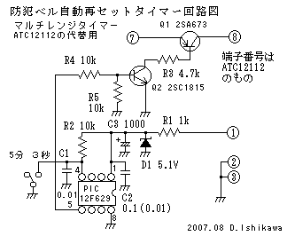
PIC12F629を使って防犯ベル用自動再セットタイマーを作りました。そのアセンブラープログラムを紹介します。防犯ベルが動作してから一定時間後に停止するようにします。更に停止した後も何度でも動作するように防犯ベルを自動再設定するようにしています。
PIC12F629を使った防犯ベル用自動再セットタイマー

防犯ベルは泥棒が入ろうとした時ベルが鳴りますが、一般的にはベルは鳴り続けます。
これでは周りに迷惑を掛けて不便なので一定時間後に停止するようにしました。
更に停止した後も何度でも動作するように防犯ベルを自動で再設定するようにしました。
しかし製作当時はタイマーの適当なのが見つからなかったので、ナショナルのマルチ レンジタイマー楽天 ATC12112をONモードの5分にして使っていました。
その後、 PICマイコンが使えるようになったので、このATC12112のタイマーをPIC12F629に置き換えてみました。回路やプログラムが簡単にうまくできましたので紹介します。
回路は簡単ですが、プログラムを作らないと動作しません。プログラムは全てアセンブラーで書いています。アセンブラーは一見すると難しそうですが、使えるようになると、細かい動作を簡単に記述できるようになります。
PIC12F629を使ったアセンブラープログラム
; Filename:	bell_timer.asm
; Date:		2007.08.03
; File Version:	1.0
; Bell Timer 3sec. 5min
; Author:		D.Ishikawa
;**********************************************************************
; Files required:
;**********************************************************************
;PICは12F629
;GPIO,2	タイマー出力ポート
;GPIO,3	タイマーの時間を決める入力ポート
;GPIO,3がLの時テスト用3秒タイマーとなります。
;GPIO,3がHの時5分タイマーとなります。
;**********************************************************************

	list	p=12f629		;list directive to define processor
	#include	<p12f629.inc>	;processor specific variable definitions

	errorlevel	-302	; suppress message 302 from list file

	__CONFIG _CP_ON & _CPD_ON & _BODEN_ON & _MCLRE_OFF & _WDT_OFF & _PWRTE_ON & _INTRC_OSC_NOCLKOUT

#define	OUT_TMR	GPIO,2	;タイマー出力ポート
#define	IN_P	GPIO,3	;入力ポート

;***** VARIABLE DEFINITIONS
w_temp		EQU	0x20	;variable used for context saving
status_temp	EQU	0x21	;variable used for context saving

TMP_CNT1		EQU 0x22
TMP_CNT2		EQU 0x23
TMP_CNT3		EQU 0x24
TMP_CNT4		EQU 0x25
;**********************************************************************
	ORG	0x000	;processor reset vector
	goto	main	;go to beginning of program

	ORG	0x004	;interrupt vector location
	movwf	w_temp	;save off current W register contents
	movf	STATUS,w	;move status register into W register
	movwf	status_temp	;save off contents of STATUS register

;isr code can go here or be located as a call subroutine elsewhere

	movf	status_temp,w	;retrieve copy of STATUS register
	movwf	STATUS		;restore pre-isr STATUS register contents
	swapf	w_temp,f
	swapf	w_temp,w		;restore pre-isr W register contents
	retfie	;return from interrupt

;these first 4 instructions are not required if the internal oscillator is not used

main
	call	0x3FF		;retrieve factory calibration value
	bsf	STATUS,RP0	;set file register bank to 1
	movwf	OSCCAL		;update register with factory cal value
	bcf	STATUS,RP0	;set file register bank to 0

;remaining code goes here

	bcf	STATUS,RP0	;set file register bank to 0
	bcf	STATUS,RP1	;set file register bank to 0

	clrf	INTCON		;割り込み禁止

	clrf	GPIO		;GPIO初期化

	bsf	STATUS,RP0	;バンク1に切替
	clrf	TRISIO		;GPIOを出力に設定
	bsf	TRISIO,3		;GP3を入力に設定

	clrf	IOC		;I/O状態変化チェック解除
	movlw	b'10000000'	;プルアップ無し、エッジ割り込み無し、タイマー0は内部クロック
	movwf	OPTION_REG	;

	bcf	STATUS,RP0	;バンク0に

	bcf	OUT_TMR		;OUT_TMRを0に

	btfsc	IN_P		;入力ポートチェック
	goto	_5MIN		;Hなら _5MIN へ

_3SEC
	call	DLY_500
	call	DLY_500
	call	DLY_500
	call	DLY_500
	call	DLY_500
	call	DLY_500
SET3	bsf	OUT_TMR	;OUT_TMRを1に
	goto	SET3

_5MIN
	call	DLY_5MIN
SET5	bsf	OUT_TMR	;OUT_TMRを1に
	goto	SET5

;Delay Routine

DLY_5MIN			;5分
	movlw	d'5'		;1*5=5min
	movwf	TMP_CNT4
DLY_4			;60S
	movlw	d'120'		;0.5*120=60S
	movwf	TMP_CNT3
DLY_3
	call	DLY_500
	decfsz	TMP_CNT3,f
	goto	DLY_3
	decfsz	TMP_CNT4,f
	goto	DLY_4
	return

DLY_500			;500mS
	movlw	d'250'		;2mS*250=500mS
	movwf	TMP_CNT2
DLY_2			;2mS	;    DLY_2 loop	DLY_2 を一巡する時間は 6 + 8*249 + 2 = 2000μS
	movlw	d'249'		;	(1)		1cycle=1μS
	movwf	TMP_CNT1		;	(1)
	nop			;	(1)
	nop			;	(1)
	nop			;	(1)
	nop			;	(1)
DLY_1			;  DLY_1 loop
	nop			;1	 1
	nop			;1	 1
	nop			;1	 1
	nop			;1	 1
	nop			;1	 1
	decfsz	TMP_CNT1,f	;1	 2	(TMP_CNT1が0になると2サイクル)
	goto	DLY_1		;2		(12F629の goto は2サイクル)
	decfsz	TMP_CNT2,f	;	 1
	goto	DLY_2		;	(2)
	return

;initialize eeprom locations

	ORG	0x2100
	DE	0x00, 0x01, 0x02, 0x03

	END			;directive 'end of program'
アセンブラープログラムの使い方
ファイル名をbell_timer.asm等にして保存して使ってください。